 |
|||
|
|
|||
|
Page Title:
Figure 23. Starting motor, exploded view. |
|
||
| ||||||||||
|
|
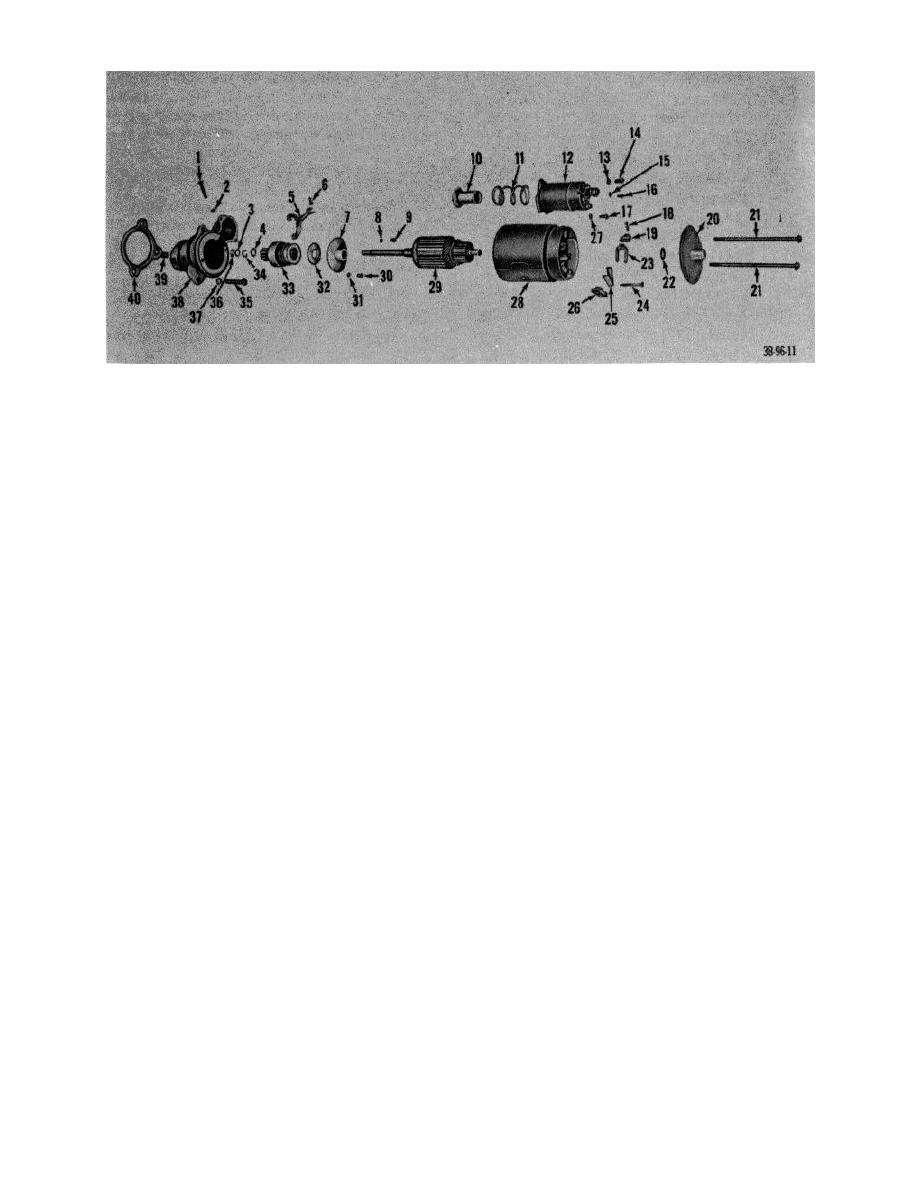 1
Bolt, shoulder, drive lever
21
Bolts
2
Washer
22
Washer, brake, commutator end
3
Collar, thrust
23
Holder, brush, ground
4
Collar, pinion top
24
Pin
5
Lever, assembly, drive
25
Spring, brush
6
Pin, spring, lever-to-plunger
26
Holder, brush, insulated
7
Bearing, sleeve, center
27
Lockwasher
8
Lockwasher
28
Housing
9
Screw
29
Armature
10
Plunger
30
Screw
11
Spring, compression, plunger return
31
Lockwasher
12
Relay, solenoid, starter
32
Washer
13
Lockwasher
33
Drive assembly
14
Screw
34
Ring, retainer
15
Washer
35
Capscrew
16
Screw
36
Nut
17
Screw
37
Lockwasher
18
Screw, brush attaching
38
Housing, drive
19
Brush, contact
39
Bearing, sleeve, drive end
20
Frame, commutator end
40
Adapter, starting motor
Figure 23. Starting motor, exploded view.
brushes if worn beyond one-half original
(7) Remove screws (86) and washers (87) that
length.
attach bearing plate (12) to drive end frame and
(c) Be certain that brush holders are not bent or
remove plate.
(8) Remove gasket (11), bearing (10), felt retaining
damaged in any manner and that brush
plate (9) and washer (8) from drive end frame
springs are not corroded or distorted. Check
(7).
for brush spring tension of 28 ounces.
c. Cleaning. Using air hose or clean cloths, remove
(d) Using a testing device consisting of a lamp
all dirt from component parts of generator before
wired in series with two probes and the source
inspecting them.
of electricity, inspect the field coils for proper
d. Inspection, Testing, and Repair.
ground. Before testing, be sure brushes are
(1) Frame, field coils, brushes, springs, leads,
not touching frame or pole shoes, then
proceed as follows: Touch one probe to
connections, and terminal stud.
terminal stud and the other probe to an
(a) Inspect field coils for worn or frayed
unpainted spot on the frame. Should the lamp
insulation; corroded, loose, or burned terminal
light, the current in the field coils is being
stud assembly; and loose or corroded
grounded before it completes the circuit.
connections.
(b) Inspect brushes for excessive wear, broken or
frayed leads, and oil saturation. Replace
AGO 7010A
34
|
|
Privacy Statement - Press Release - Copyright Information. - Contact Us |
