 |
|||
|
|
|||
|
Page Title:
Figure 11. Punch marks on cylinder block and crankshaft bearing caps. |
|
||
| ||||||||||
|
|
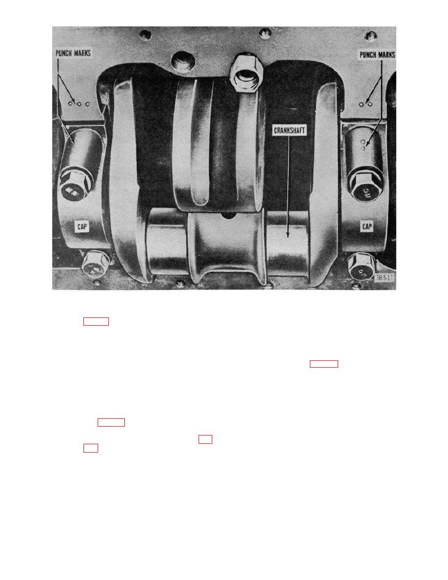 Figure 11. Punch marks on cylinder block and crankshaft bearing caps.
specifications Check clearance by
(8)
Remove piston pin retaining rings (8,
inserting a well oiled brass shim (1/2
inch wide by 1 inch long by 0.002 inch
pins (25) from connecting rods and
thick)
between
bearings
and
crankshaft journals.
Using a
b. Inspection and Repair.
torque wrench, tighten cap bolt nuts
(1) Clean all parts with SD.
(18, fig. 10) to 85 to 40 pound-feet of
(2) Inspect for pitting, scoring, or excessive
pressure, and rotate crankshaft. If
wear of connecting rod sleeve
there i stiff resistance while the
bearing.
crnilrh-ft is turning, the bearing
(3) Check alinement of each connecting rod
clearance is not excessive.
with a rod lining fixture and straighten
each connecting rod with arbor press
certain that connecting rod bearing seats are clean.
or connecting rod straightening tool
(B, fig. 13), as necessary, to bring
Coat connecting rod bearings with OE and make certain
that bearing lugs engage slots and that oil holes are
upper and lower bores parallel within
alined.
0.002 inch and to remove twist (A, fig.
(4)
Replace bearings if recommended
clearance (0.001 inch) is not within
AGO 7010A
19
|
|
Privacy Statement - Press Release - Copyright Information. - Contact Us |
