 |
|||
|
|
|||
|
Page Title:
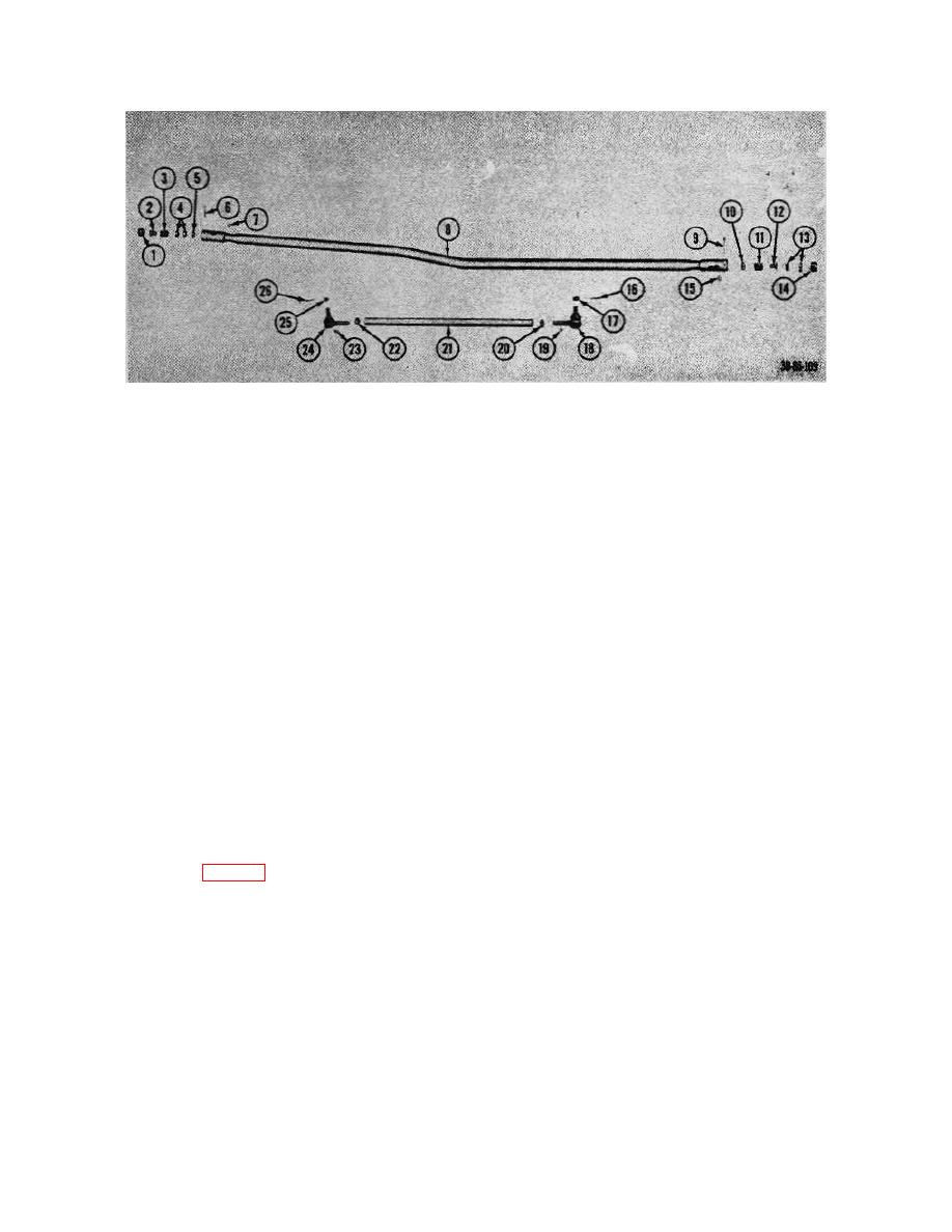
Figure 82. Drag link and tie rod assemblies, exploded view. |
|
||
| ||||||||||
|
|
 TM 10-3930-222-20
1
Plug, end
14
Plug, end
2
Bumper, spring
15
Fitting, lubrication
3
Spring
16
Pin, cotter
4
Seat, ball
17
Nut, castellated
5
Seat
18
End, tie rod
6
Pin, cotter
19
Fitting, lubrication
7
Fitting, lubrication
20
Jamnut
8
Link, drag
21
Rod, tie
9
Pin, cotter
22
Jamnut
10
Seat
23
Fitting, lubrication
11
Spring
24
End tie rod
12
Bumper, spring
25
Nut, castellated
13
Seat, ball
26
Pin, cotter
Figure 82. Drag link and tie rod assemblies, exploded view.
(4) Using a suitable toe-in gage, check to be
(5) Repeat procedures (2) through (4) above
sure there is 0o toe-in.
and remove the cylinder from ball stud
(31) on the frame of the truck.
(5) Tighten the jamnuts when the proper
adjustment has been made.
(6) Unscrew the nut (32) and remove the ball
stud (31) from the frame if necessary.
76. Steering Booster Cylinder
b. Installation. Reverse procedures in a above and
then make adjustment in c below.
a. Removal.
(1) Disconnect and cap the hydraulic hoses (7
and 10, fig. 83) at the cylinder assembly
c. Adjustment.
When replacing the cylinder
(24).
assembly in the truck, adjustment must be made to the
ball socket end of the cylinder assembly to give an
(2) Remove the cotter pin (21) from the ball
equal turning radius to the wheels. Adjust as follows:
socket end (16).
(1) Center the wheels by turning the steering
(3) Remove the end plug (20) and half of ball
wheel an equal number of turns to the
seat (19) from the ball socket end and the
right and to the left and returning the
lift steering booster cylinder from the
steering wheel to the center position.
center arm on the steering axle.
(2) Loosen the clamp on the ball socket end
(4) Remove the remaining half of ball seat
of the steering booster cylinder.
(19Y, spring (18), and seat (17) from the
ball socket end.
127
|
|
Privacy Statement - Press Release - Copyright Information. - Contact Us |
