 |
|||
|
|
|||
|
Page Title:
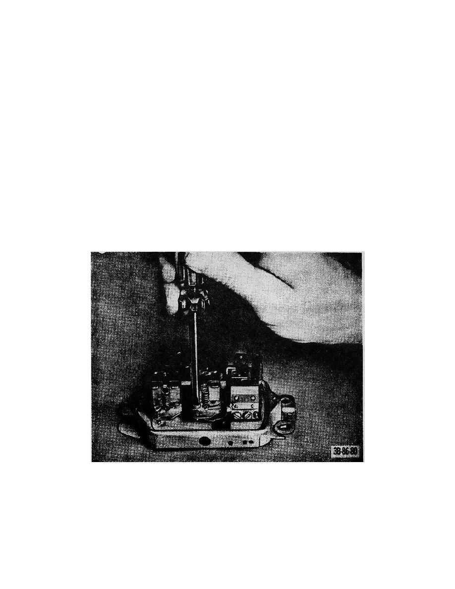
Figure 53. Adjusting current regulator setting. |
|
||
| ||||||||||
|
|
 TM 10-3930-222-20
(4)
Remove the nut and star washer from the
Note. The wire or string remaining in steering post
switch and remove the switch from the truck.
will be used to install a new horn cable assembly.
b. Installation. Reverse procedures in a above.
b. Installation.
54. Instruments and Gages
(1)
Attach the horn cable assembly to the wire or
string.
The instruments and gages (fig. 66) may be removed
(2)
Pull the horn cable assembly through the
by disconnecting wiring from the Individual instrument or
steering post.
gage and removing the instrument or gage from the
(3)
Reverse procedures (1) through (5) in a
truck. Tag the wires for proper installation.
above.
55. Temperature Sending Unit
53. Light Switch
The temperature sending unit, located beside the engine
oil filter on the cylinder head is removed as follows:
a. Removal.
a. Removal.
(1)
Disconnect the ground cable at the battery.
(1)
Disconnect the lead wire at the unit.
(2)
Disconnect and tag all electrical leads at the
(2)
Unscrew and remove the sending unit from
light switch (fig. 66).
the engine block.
(3)
Remove the screw that secures the handle to
the switch and remove the handle.
b. Installation. Reverse procedures in a above.
Figure 53. Adjusting current regulator setting.
94
|
|
Privacy Statement - Press Release - Copyright Information. - Contact Us |
