 |
|||
|
|
|||
|
Page Title:
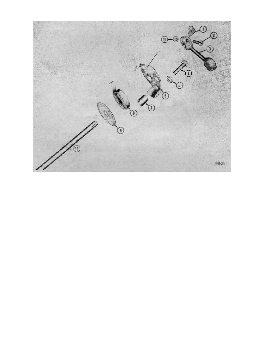
Figure 31. Heat control valve, exploded view. |
|
||
| ||||||||||
|
|
 TM 10-3930-222-20
1
Key
7
Spacer, cover
2
Screw
8
Thermostat
3
Counterweight
9
Washer, shield
4
Capscrew
10
Shaft
5
Lockwasher
11
Nut
6
Cover, thermostat
Figure 31. Heat control valve, exploded view.
Section VII. COOLING SYSTEM (GROUP 05)
the engine and through the cycle as long as the
35. General
thermostat remains open.
The cooling system consists of a radiator, a water pump,
36. Radiator
a fan and a thermostat. The coolant picks up heat from
the crankcase and cylinder head as it is circulated by the
water pump through the engine. When the coolant
a. Inspection and External Cleaning.
temperature rises sufficiently, the thermostat opens and
(1) Raise the hood and remove radiator grill.
permits the coolant to circulate to the radiator, where,
with the help of the fan, the heat is dissipated to the
atmosphere. The cooled liquid then circulates back to
72
|
|
Privacy Statement - Press Release - Copyright Information. - Contact Us |
