 |
|||
|
|
|||
|
Page Title:
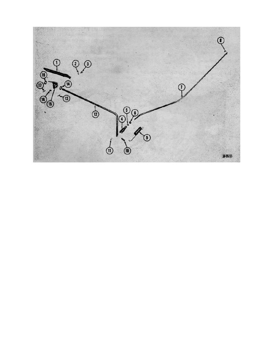
Figure 28. Throttle pedal linkage, exploded view. |
|
||
| ||||||||||
|
|
 TM 10-3930-222-20
1
Pedal, throttle
10
Pin, straight head
2
Lockwasher
11
Pin, cotter
3
Capscrew
12
Crank, throttle
4
End, rod
13
Pin, roll
5
Washer, flat
14
Washer, flat
6
Nut
15
Lever, throttle pedal
7
Rod, throttle
16
Nut
8
Clip, clevis
17
Pin, roll
9
Spring
18
Washer, flat
Figure 28. Throttle pedal linkage, exploded view.
Section VI. EXHAUST SYSTEM (GROUP 04)
32. General
33. Muffler and Exhaust Elbow
The exhaust system consists of a muffler
connected to the manifold assembly by an exhaust
holes, cracks, dents, and secure- mounting.
elbow. A heat control valve, located in the exhaust
b. Removal.
manifold, deflects the hot gases in the manifold
(1) Remove the capscrews (fig.
29) and
assembly upon starting to permit quicker vaporization of
lockwashers that secure the muffler to the
the fuel. As the manifold assembly reaches normal
manifold exhaust elbowv.
operating temperature, the heat control valve gradually
(2) Remove the muffler (fig. 30) and gasket from
opens.
the truck.
69
|
|
Privacy Statement - Press Release - Copyright Information. - Contact Us |
