 |
|||
|
|
|||
|
Page Title:
Section III. OPERATION UNDER USUAL CONDITIONS |
|
||
| ||||||||||
|
|
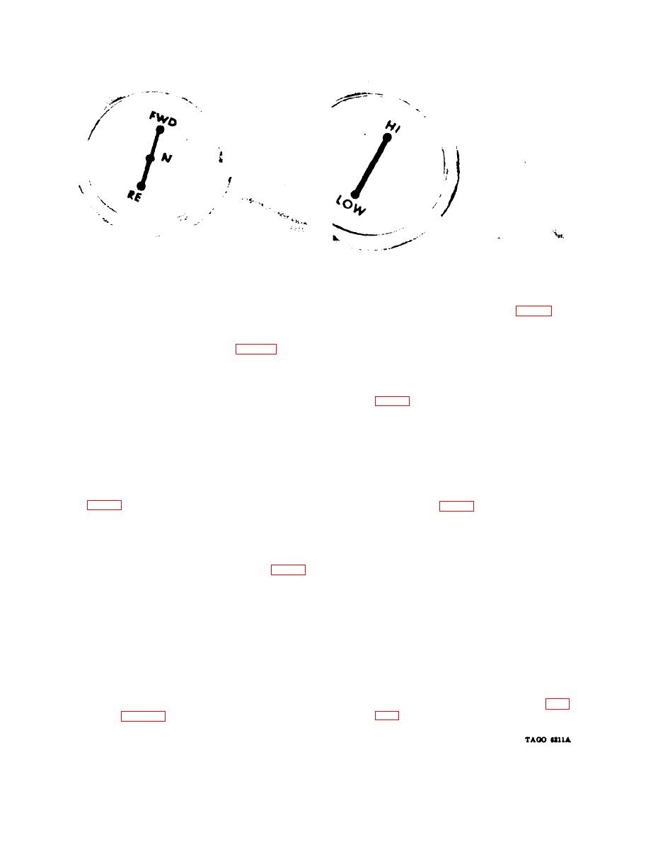
 Figure 6. Direction control lever.
Figure 7. High- and low-speed lever.
move the forks closer together. Turn the crank
counterclockwise to move the forks further
apart.
located on the instrument panel at the right of
12. Instruments
the water temperature gage. This gage indi-
cates the amount of gasoline in the fuel tank.
The capacity of the fuel tank is 14 gallons.
cated on the instrument panel to the left and
e. Converter Oil Temperature Warning
above the steering column. The ammeter indi-
Light. The converter oil temperature warning
cates the amount of current flowing to or being
withdrawn from the storage battery. When the
light (8, fig. 4) is located on the instrument
engine is started, the needle will move momen-
panel to the left of the ignition switch (9). The
tarily far to the charge side of the dial and then
warning light glows red when the transmission
return to a center position or slightly to the
temperature is too high for safe operation of
charge side. If the ammeter shows a constant
the truck. If the light glows, stop the engine
discharge, stop the engine and report the
immediately and report the trouble to the
trouble to the proper authority.
proper authority.
b. Oil Pressure Gage. The oil pressure gage
f. Water Temperature Gage. The water
(3, fig. 4) is located on the instrument panel
temperature gage (5, fig. 4) is located on the
at the right of the ammeter. This gage indi-
instrument panel to the right of the hour
cates the pounds per square inch of oil pressure
meter. This gage indicates engine coolant
in the engine lubrication system. Normal op-
temperature on a dial marked C, NORMAL, and
erating pressure is 20 to 30 psi at 2,000 rpm.
H. During operation, the needle should move
into the NORMAL area. If the needle fails to
move into this area after the engine has been
is located on the instrument panel to the right
operated for a reasonable time, or moves into
of the oil pressure gage. This meter indicates
the H area, stop the engine and report the
the total number of hours that the engine has
trouble to the proper authority.
been in operation.
OPERATION UNDER USUAL CONDITIONS
Section III.
b. Instructions.
13. Starting
a. Before-Operation Services. Perform the
(1) Set the handbrake by pulling up and
back on the handbrake lever (par.
before-operation services listed in the operator's
1 1h ) .
checklist (par. 24).
10
|
|
Privacy Statement - Press Release - Copyright Information. - Contact Us |